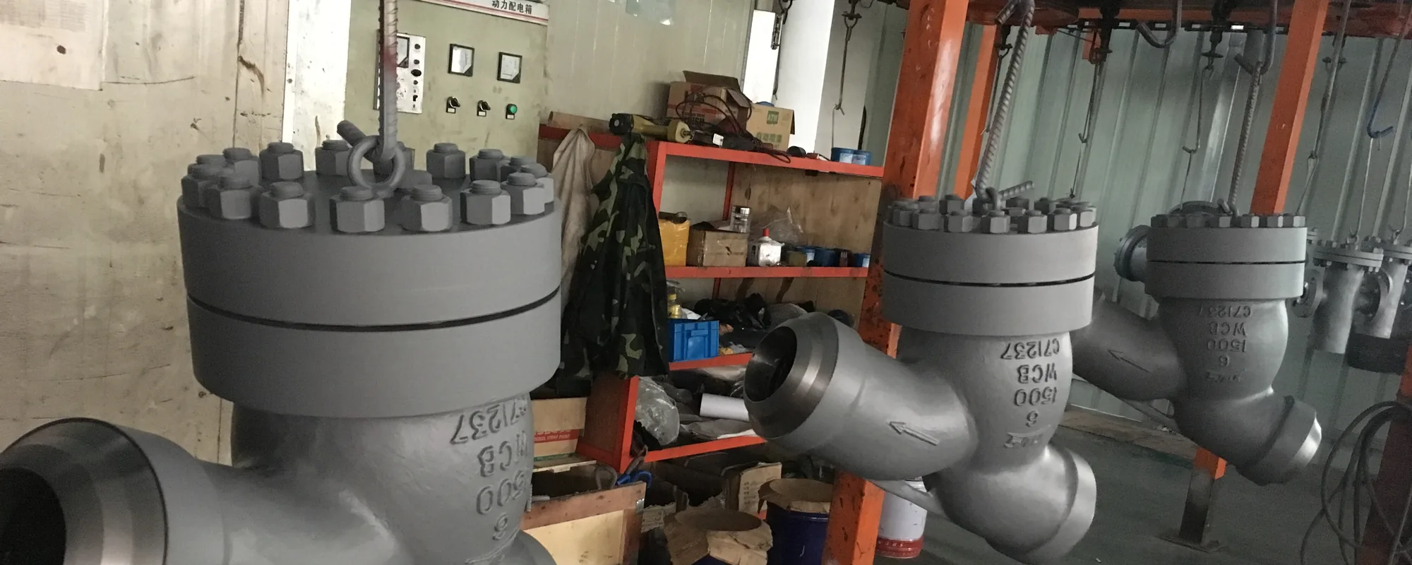
A pressure seal bonnet comes apart differently from a bolted bonnet, and the difference catches people out. The bonnet cannot be lifted off. It has to go down into the body before it can come out.
This page describes the general principle. It does not replace the manufacturer’s procedure for your specific valve, and it does not address isolation, draining, cooling or permit requirements, which are your plant’s responsibility and must be satisfied first.
Why it comes apart downward
The bonnet was inserted into the body from inside during assembly, which means it is smaller than the bore it passed through. It is held up by a segmental retainer ring sitting in a groove in the body bore, with the seal ring and thrust ring stacked between the retainer and the bonnet shoulder.
To free the retainer segments, the load on them has to be released. The only way to do that is to push the bonnet down, away from the retainer. Then the segments come out, and the bonnet - now unobstructed - can be lifted through the bore.
Trying to lift first, against the retainer, is how retainer grooves get damaged.
General sequence
Disassembly
- Confirm isolation, depressurisation, draining and cooling per plant procedure. A pressure seal valve retains a cavity of fluid; this is not optional.
- Release the gland studs and back off the gland. The gland preload is part of what holds the seal stack in compression.
- Apply downward force to the bonnet through the designed jacking arrangement. Most valves have provision for this; using an undesigned load path damages the bonnet or the stem.
- With the retainer segments free, remove them. Note their orientation - some are not symmetrical.
- Remove the thrust ring and the seal ring. Expect the seal ring to be deformed; it has been under compression at temperature.
- Lift the bonnet out through the body bore.
Reassembly
- Clean the taper in the body bore and the bonnet shoulder. Any debris on these surfaces prevents the seal ring seating evenly, and the leak that results will be blamed on the ring.
- Fit a new seal ring. See below.
- Insert the bonnet, fit the thrust ring, then the retainer segments in their correct orientation.
- Apply the specified assembly preload through the gland studs, in the specified sequence and to the specified value. This is what makes the joint tight at low pressure before the self-energizing effect takes over.
- Fit new packing and set the gland.
- Pressure test before returning to service.
The seal ring is a single-use part
Flexible graphite takes a permanent set under compression at temperature. A ring that has been in service has already conformed to its taper and lost the resilience it needs to seal against a fresh assembly.
Reusing it is the single most common cause of a pressure seal valve that leaks after an overhaul when it did not before. Order the replacement ring with the overhaul kit. It is an inexpensive part and it is the whole joint.
The retainer segments and thrust ring are normally reusable, but should be inspected for deformation, galling on the load faces and cracking. Replace them if there is any doubt - a retainer segment that fails in service releases the bonnet.
Assembly preload matters more than it looks
The self-energizing effect needs pressure to work. At zero pressure there is nothing energising the joint except the preload applied at assembly through the gland studs.
Get it wrong and you see a confusing symptom: the valve weeps at low pressure during startup, then seals perfectly once the line comes up to operating pressure. The instinct is to suspect the seal ring. Usually it is the preload.
The preload value and the tightening sequence come from the manufacturer. They are not a general figure and they should be in the documentation supplied with the valve. If they were not supplied, ask for them before the first overhaul rather than during it.
The rest of the valve
Packing. Replace rather than adjust. Flexible graphite packing that has been in service at temperature has consolidated; over-tightening a consolidated set adds stem friction without adding sealing.
Back seat. On gate and globe valves, inspect it while the bonnet is out. It is easy to check and rarely looked at. A damaged back seat removes a maintenance option you may want later.
Seat and closure member. Inspect the Stellite overlay for wire-drawing, cracking and impingement damage. Light damage can be lapped. Deep damage means re-overlaying, which needs the correct procedure and PWHT for the body material - on F91 this is workshop work, not site work.
Guide surfaces. On a globe or stop-check, record the guide clearance. On a check valve, record the hinge pin and bushing clearance. These are the numbers that tell you whether the valve will chatter, and they are worth trending across outages.
What to keep
For each valve, keep the assembly preload value, the seal ring part number, the guide or hinge clearances measured at each overhaul, and the condition of the overlay. Four data points, and together they tell you whether a valve is stable or degrading - which is far more useful at the next outage planning meeting than a note saying the valve was overhauled.