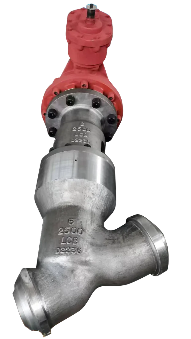
Dervos valve · Product specification
Stop-Check Valve
A globe body where the disc is free to lift under forward flow but can be screwed down to isolate. Two functions, one pressure boundary, one flange pair.
- Size
- NPS 2-16 (DN 50-400)
- Pressure class
- Class 900 - 2500
- Body material
- A182 F22, F91, F92; A105 for lower temperature
- End connection
- BW to ASME B16.25, flanged RF or RTJ
Catalogue ranges for initial selection. Final rating and configuration are confirmed against your project specification.
Have an MTO or datasheet? Send it with size, class, material, quantity and required delivery.
01 / Selection data
Technical specifications
Use these ranges to shortlist the valve. Values marked “confirm per order” depend on the selected size, material or project standard.
Swipe or scroll sideways to view the full table.
| Parameter | Specification | Basis |
|---|---|---|
| Size | NPS 2-16 (DN 50-400) | Catalogue range |
| Pressure class | Class 900 - 2500 | Catalogue range |
| Design temperature | up to 620 °C / 1148 °FY-globe stop check construction. The limit is set by the body grade and the B16.34 table. | Configuration dependent |
| Medium | Superheated and saturated steam | Catalogue range |
| Body material | A182 F22, F91, F92; A105 for lower temperature | Catalogue range |
| Disc | Piston or plug type, free-floating on the stem | Catalogue range |
| Trim | F6NM / 422SS, Stellite 6 hardfaced | Catalogue range |
| Bonnet | Self-energizing pressure seal | Catalogue range |
| End connection | BW to ASME B16.25, flanged RF or RTJ | Catalogue range |
| Orientation | Per approved GA drawing | Confirm per order |
02 / Engineering
Valve design & materials
Free-floating disc with screw-down override
The stem contacts the disc but is not connected to it. Backed off, the disc behaves as a lift check. Screwed down, it becomes a positively seated globe valve. The transition is what makes this valve useful and also what makes it unsuitable for throttling.
Guided disc travel
The disc is guided over its lift so it does not cock in the bore under fluctuating flow. Guide clearance is recorded at assembly, because it is the parameter that determines whether the valve chatters in service.
Pressure seal bonnet
Same self-energizing arrangement as the rest of the range. On a boiler outlet valve, which sees the full startup and shutdown cycle of its boiler, the absence of a bolted joint to relax is a direct reliability benefit.
Stem sized for the closing case
The stem has to force the disc closed against full forward flow if the valve is shut while the boiler is on line. That, not the open condition, sets the stem and operator sizing.
Reference material configurations
Material combinations are examples for selection; the final bill of materials is agreed for each order.
Swipe or scroll sideways to view the full table.
| Part | Carbon steel | Alloy steel | F91 / F92 |
|---|---|---|---|
| Body | A105 / A105N | A182 F11, F22 | A182 F91, F92 |
| Seat ring | 13Cr + Stellite 6 | 13Cr + Stellite 6 | F91 + Stellite 6 |
| Disc (plug type) | A105 + Stellite 6 | F11 / F22 + Stellite 6 | F91 + Stellite 6 |
| Disc nut / stem coupling | A182 F6a | A182 F6a | A182 F6NM |
| Stem | A182 F6a | A182 F6a Cl.2 | A182 F6NM / 422SS |
| Bonnet | A105 / A105N | A182 F11, F22 | A182 F91, F92 |
| Pressure seal ring | Flexible graphite + SS liner | Flexible graphite + SS liner | Flexible graphite + Inconel liner |
| Thrust ring (segmental) | A105 | A182 F11 / F22 | A182 F91 |
| Retainer segments | A105 | A182 F11 / F22 | A182 F91 |
| Gland | A105 | A182 F11 / F22 | A182 F91 |
| Stem packing | Flexible graphite | Flexible graphite | Flexible graphite, low-leakage set |
| Yoke / yoke bushing | WCB / Ni-Al bronze | WCB / Ni-Al bronze | WCB / Ni-Al bronze |
| Back seat | 13Cr overlay | 13Cr overlay | Stellite overlay |
| Handwheel | Ductile iron / carbon steel | Ductile iron / carbon steel | Ductile iron / carbon steel |
| Nameplate | AISI 304 | AISI 304 | AISI 304 |
Service fit
Where this valve is used
Typical applications
- Boiler main steam outlet to a common header
- Multi-boiler and multi-HRSG installations
- Auxiliary steam headers with several sources
- Deaerator and heater steam supply from more than one source
Selection limits to check
- Use as a throttling valve. The disc is not stem-guided over its whole travel and will chatter at partial lift.
- Reverse-direction installation. Flow direction is fixed.
- Service where the non-return function must be verified independently - a stop-check does not give position feedback on the disc.
- Horizontal installation without confirming the disc guide arrangement; the standard configuration assumes a specific orientation.
Quality assurance
Inspection & delivery documents
The inspection and test plan defines the agreed scope, hold points and witness points for your order.
Inspection scope
- Hydrostatic shell test to API 598 / MSS SP-61
- Hydrostatic or pneumatic seat test, leakage rate per specification
- Back seat test (gate and globe, where a back seat is supplied)
- PMI on all pressure-containing parts and welded overlays
- NDE per specification - RT, UT, MT or PT as applicable
- Hardness survey after post-weld heat treatment
- Dimensional inspection against approved GA drawing
- Material certification EN 10204 3.1 (3.2 on request)
- Visual and functional check, full stroke on the manual operator
- Disc lift and free-fall check through the full travel
- Guide clearance record at assembly
Document package
- Product datasheet
- General arrangement (GA) drawing
- Inspection & Test Plan (ITP)
- Material test certificate (MTC) EN 10204 3.1
- Hydrostatic and seat test report
- PMI report
- NDE reports as applicable
- Heat treatment charts
- Dimensional report
- Packing list and preservation record
Reference framework
Applicable standards
Pressure-temperature ratings, materials, wall thickness, testing and marking. This is the base rating standard for the valve - it is what fixes the allowable pressure at your design temperature.
Face-to-face and end-to-end dimensions. Relevant when the valve replaces an existing one or has to drop into a fixed spool.
Butt welding end preparation, including bore and bevel geometry for the matching pipe schedule.
Inspection and pressure testing - which tests are mandatory, test durations and allowable leakage. We state the shell and seat test scheme on the ITP.
Alternative pressure testing scheme for steel valves, used where the project specification calls for it instead of API 598.
Marking of the body and the nameplate - size, class, material heat, figure number and flow direction where applicable.
Buying questions
Frequently asked questions
Is a stop-check the same as a globe valve with a check function bolted on?
No. The disc is deliberately not connected to the stem, which is a different internal arrangement from a globe valve. You cannot convert one to the other in the field, and a globe valve with the disc nut removed is a failed valve, not a stop-check.
Can I use one instead of a separate gate valve and check valve?
That is exactly the intent - one body, one pair of welds, one item to maintain. The trade-off is that you lose full-bore flow and you cannot independently verify the check function. On a boiler outlet the trade is usually worth it; on a main line where you need full-bore isolation it is not.
What orientation should it be installed in?
It depends on the disc arrangement supplied. Do not assume - the orientation is on the GA drawing, and it needs to be confirmed at the approval stage rather than discovered during installation.