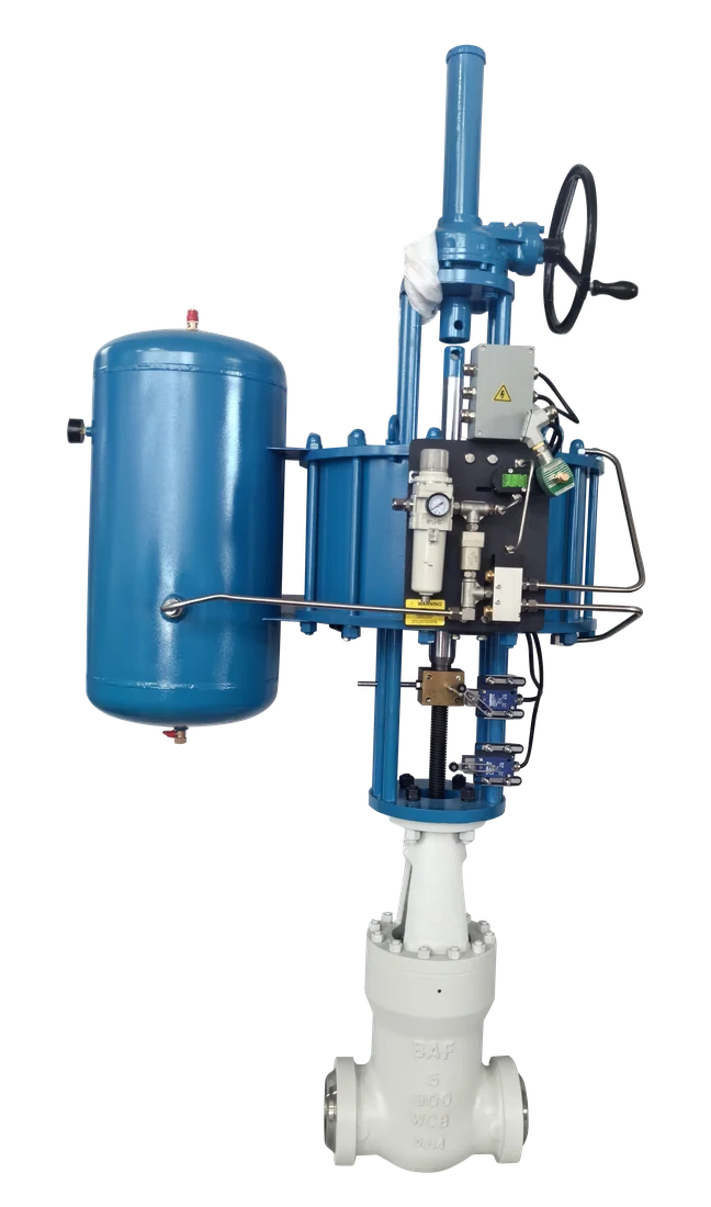
Dervos valve · Product specification
Pressure Seal Gate Valve
Self-energizing bonnet gate valve for high-pressure steam and feedwater isolation. Seal tightness increases with line pressure rather than depending on bolt load.
- Size
- NPS 2-24 (DN 50-600)
- Pressure class
- Class 600 - 4500
- Body material
- A105, A182 F11, F22, F91, F92
- End connection
- BW to ASME B16.25, SW, flanged RF or RTJ
- Operation
- Handwheel, bevel gear, electric or pneumatic actuator
Catalogue ranges for initial selection. Final rating and configuration are confirmed against your project specification.
Have an MTO or datasheet? Send it with size, class, material, quantity and required delivery.
01 / Selection data
Technical specifications
Use these ranges to shortlist the valve. Values marked “confirm per order” depend on the selected size, material or project standard.
Swipe or scroll sideways to view the full table.
| Parameter | Specification | Basis |
|---|---|---|
| Size | NPS 2-24 (DN 50-600)Larger sizes are project-dependent and confirmed case by case. | Catalogue range |
| Pressure class | Class 600 - 4500Class 4500 is confirmed per item against material and size. | Catalogue range |
| Design temperature | up to 650 °C / 1200 °FThe actual limit is set by the body material and the ASME B16.34 rating table, not by the valve type. | Configuration dependent |
| Medium | Superheated steam, saturated steam, feedwater, condensate | Catalogue range |
| Body material | A105, A182 F11, F22, F91, F92Grade is selected from the design temperature - see the material matrix. | Catalogue range |
| Trim material | 13Cr / F6a, hardfaced with Stellite 6 | Catalogue range |
| Bonnet | Self-energizing pressure seal, segmental retainer | Catalogue range |
| Wedge | Flexible wedge, solid wedge on request | Catalogue range |
| End connection | BW to ASME B16.25, SW, flanged RF or RTJ | Catalogue range |
| Operation | Handwheel, bevel gear, electric or pneumatic actuatorGear operation is normally applied from NPS 8 upward, sooner on Class 2500. | Catalogue range |
| Stem | Rising stem, OS&Y, forged and back-seated | Catalogue range |
| Packing | Flexible graphite with anti-extrusion rings | Catalogue range |
| Face-to-face | ASME B16.10 | Catalogue range |
| Leakage class | Per API 598 or project specificationZero leakage is not a specification. State the class you need and we confirm against it. | Confirm per order |
02 / Engineering
Valve design & materials
Self-energizing bonnet joint
The bonnet enters the body from inside and is held by a segmental retainer ring. Internal pressure drives the bonnet up into a tapered graphite seal ring, so seating force is proportional to line pressure. There is no bolted flange to relax under thermal cycling.
One-piece forged body
The pressure-containing body is machined from a single forging, not assembled from cast sections. Grain flow follows the shape of the part and there is no casting porosity to find during RT. Where the specification calls for "integral forged", we confirm exactly which parts are integral rather than treating the term as a synonym for one-piece.
Flexible wedge
A circumferential groove lets the two wedge faces flex independently. This absorbs body distortion during thermal transients and reduces the risk of the wedge binding in the seat after a hot shutdown - the classic failure mode for a solid wedge in main steam service.
Stellite 6 hardfaced seating
Seat rings and wedge faces carry a cobalt-based overlay applied by PTA or manual weld deposit, then machined and lapped. Overlay thickness after machining and the hardness range are recorded and available on the test report.
Back seat
A hardfaced back seat allows the packing to be isolated with the valve fully open. This is a maintenance provision, not a licence to repack a live line - we state that limit rather than implying online repacking is approved.
Anti-blowout stem
The stem is forged with a shoulder that cannot pass through the bonnet bore. Failure of the gland assembly does not release the stem.
Reference material configurations
Material combinations are examples for selection; the final bill of materials is agreed for each order.
Swipe or scroll sideways to view the full table.
| Part | Carbon steel | Alloy steel | F91 / F92 |
|---|---|---|---|
| Body | A105 / A105N | A182 F11, F22 | A182 F91, F92 |
| Seat ring | 13Cr + Stellite 6 | 13Cr + Stellite 6 | F91 + Stellite 6 |
| Wedge (flexible) | A105 + Stellite 6 | F11 / F22 + Stellite 6 | F91 + Stellite 6 |
| Stem | A182 F6a | A182 F6a Cl.2 | A182 F6NM / 422SS |
| Bonnet | A105 / A105N | A182 F11, F22 | A182 F91, F92 |
| Pressure seal ring | Flexible graphite + SS liner | Flexible graphite + SS liner | Flexible graphite + Inconel liner |
| Thrust ring (segmental) | A105 | A182 F11 / F22 | A182 F91 |
| Retainer segments | A105 | A182 F11 / F22 | A182 F91 |
| Gland | A105 | A182 F11 / F22 | A182 F91 |
| Gland flange | A105 | A105 | A182 F91 |
| Stem packing | Flexible graphite | Flexible graphite | Flexible graphite, low-leakage set |
| Gland eyebolt / pin | A193 B7 / A194 2H | A193 B16 | A193 B16 |
| Yoke | A105 / WCB | A105 / WCB | A105 / WCB |
| Yoke bushing | Ni-Al bronze | Ni-Al bronze | Ni-Al bronze |
| Back seat | 13Cr overlay | 13Cr overlay | Stellite overlay |
| Handwheel | Ductile iron / carbon steel | Ductile iron / carbon steel | Ductile iron / carbon steel |
| Nameplate | AISI 304 | AISI 304 | AISI 304 |
03 / Reference dimensions
Dimensions & approximate weight
Typical reference values only. Request the approved GA drawing and confirmed weight for your selected class and configuration.
Swipe or scroll sideways to view the full table.
| NPS | DN | Face to face / end to end | Approx. weight |
|---|---|---|---|
| NPS 2 | DN 50 | 368 mm | ~55 kg |
| NPS 3 | DN 80 | 470 mm | ~105 kg |
| NPS 4 | DN 100 | 546 mm | ~180 kg |
| NPS 6 | DN 150 | 705 mm | ~390 kg |
| NPS 8 | DN 200 | 832 mm | ~700 kg |
| NPS 10 | DN 250 | 991 mm | ~1150 kg |
| NPS 12 | DN 300 | 1130 mm | ~1750 kg |
| NPS 16 | DN 400 | 1410 mm | ~3200 kg |
Service fit
Where this valve is used
Typical applications
- Main steam and reheat steam lines
- Boiler feedwater and feedwater heater isolation
- HP/IP turbine bypass isolation
- Boiler drain, blowdown and startup vent lines
- HRSG high-pressure circuits
Selection limits to check
- Throttling or flow control - a partially open wedge causes seat erosion. Use a globe valve.
- Slurries, particulate-laden or crystallising media that settle in the body cavity below the wedge.
- Frequent-cycling service where a quarter-turn valve is a better fit; the multi-turn stroke is slow.
- Applications requiring a certified fugitive emission class unless ISO 15848 testing has been agreed and included in the order.
Quality assurance
Inspection & delivery documents
The inspection and test plan defines the agreed scope, hold points and witness points for your order.
Inspection scope
- Hydrostatic shell test to API 598 / MSS SP-61
- Hydrostatic or pneumatic seat test, leakage rate per specification
- Back seat test (gate and globe, where a back seat is supplied)
- PMI on all pressure-containing parts and welded overlays
- NDE per specification - RT, UT, MT or PT as applicable
- Hardness survey after post-weld heat treatment
- Dimensional inspection against approved GA drawing
- Material certification EN 10204 3.1 (3.2 on request)
- Visual and functional check, full stroke on the manual operator
Document package
- Product datasheet
- General arrangement (GA) drawing
- Inspection & Test Plan (ITP)
- Material test certificate (MTC) EN 10204 3.1
- Hydrostatic and seat test report
- PMI report
- NDE reports as applicable
- Heat treatment charts
- Dimensional report
- Packing list and preservation record
Previously supplied configuration
NPS 12 Class 1500 in F91
One valve we have actually built, with the numbers from its own drawing rather than from a catalogue range. It is a Class 1500 pressure seal gate valve in F91 with a butt weld body, electric actuator and handwheel override. Your item will differ; the point is that this level of data exists per item and is issued with the order.
Configuration
| Size | NPS 12 / DN 300 |
|---|---|
| Pressure class | Class 1500 |
| Matching pipe | OD 324 mm x 26 mm wall |
| Face to face (L) | 750 mm |
| Body diameter (A) | 324 mm |
| Bore (B) | 272 mm |
| Overall height (H) | 1327 mm |
| Weight | 1435 kg |
Pressure tests
| Shell test | 38.3 MPaHydrostatic, per MSS SP-61 |
|---|---|
| Back seat test | 28.2 MPaHydrostatic |
| Seat test | 28.2 MPaHydrostatic |
| Air seat test | 0.6 MPaLow-pressure pneumatic |
Live-loaded gland with Belleville washers, Inconel 625 reinforced graphite at both the body-bonnet joint and the stem packing, and Stellite on every seating surface. The stem in A565 Gr.616HT rather than a 13Cr grade is the choice that follows from a 625 °C design temperature. Your item requires a separately approved drawing and test plan.
Reference framework
Applicable standards
Pressure-temperature ratings, materials, wall thickness, testing and marking. This is the base rating standard for the valve - it is what fixes the allowable pressure at your design temperature.
Face-to-face and end-to-end dimensions. Relevant when the valve replaces an existing one or has to drop into a fixed spool.
Butt welding end preparation, including bore and bevel geometry for the matching pipe schedule.
Flanged end dimensions and ratings, when the valve is supplied with RF or RTJ flanges rather than weld ends.
Inspection and pressure testing - which tests are mandatory, test durations and allowable leakage. We state the shell and seat test scheme on the ITP.
Alternative pressure testing scheme for steel valves, used where the project specification calls for it instead of API 598.
Marking of the body and the nameplate - size, class, material heat, figure number and flow direction where applicable.
Buying questions
Frequently asked questions
At what pressure class does a pressure seal bonnet become necessary?
There is no single threshold in the standards. In practice, bolted bonnets are used up to Class 600 and pressure seal from Class 900 upward, because above that the bolt load needed to hold a gasketed joint against thermal cycling becomes impractical. Some specifications call for pressure seal from Class 900 explicitly; others leave it to the manufacturer. Tell us which your specification says.
Is a pressure seal valve harder to maintain than a bolted bonnet?
Disassembly needs the line depressurised and a specific sequence: relieve the gland, remove the retainer segments, drive the bonnet down into the body, then lift it out. It is not more difficult, but it is different, and it usually needs the graphite seal ring replaced rather than reused. We supply the sequence with the valve.
Can you supply F91 bodies with the full PWHT and hardness records?
F91 and F92 require controlled post-weld heat treatment and a hardness survey afterwards, because both under- and over-tempering degrade creep strength. Where the order includes these grades we include the heat treatment charts and the hardness results in the document package. Ask for a sample set before you place the order.
Do you supply to a client-approved ITP with hold points?
Yes. Send your ITP with the enquiry and we mark up which points we accept as hold, witness or review, and where we would need to propose an alternative. Agreeing this before the order is placed avoids schedule loss later.
What is the difference between "integral forged" and "one-piece forged" on your datasheets?
We use "one-piece forged body" to mean the pressure-containing body is machined from a single forging. "Integral" is used only where a specific feature - for example a seat or an end connection - is formed as part of that same forging rather than welded on. The two are not interchangeable and we state which applies per size.